- Progressive dynamics power converter wiring diagram how to#
- Progressive dynamics power converter wiring diagram generator#
- Progressive dynamics power converter wiring diagram drivers#
Progressive dynamics power converter wiring diagram drivers#
With careful attention, drivers can maintain their fundamental functionalities during trips with smooth sailing and utmost reliability.īy providing efficiency, comfort, convenience, and safety, the delight of a journey can be amplified without simultaneous concerns over electricity needs. In designing and constructing an RV’s converter charger wiring diagram, it is recommended that utmost caution is taken. Accomplished expert maintenance and knowledge ensures that users increase their savings longevity significantly. Plus, any sudden error messages can be outlined and rectified easily.įinally, having a correct voltage from start to finish both reduces wastage in the battery itself and prevents unnecessary electric bills. Once an RV's electrical system functions correctly, important features, like brakes, become stable and dependable. In addition to this is the crucial advancement of security. Thus, there is intense satisfaction gained in being able to rely on one’s own system when out on a road trip. The ability to remain powered up without extra effort is a luxury of reliable engineering that brings newfound stress-free travel freedom.
Progressive dynamics power converter wiring diagram generator#
Outlets – basic sturdy charging points which most often include 120V shore power and a 240V generator product.It does so by detecting excess current levels with enough time to respond and cut power. Fuse – this specific device is designed to possess ‘overload regulation’, helping to prevent shortcircuites and prolonged faults along the line.

It charges the onboard battery and stores power until registered by the AC source.

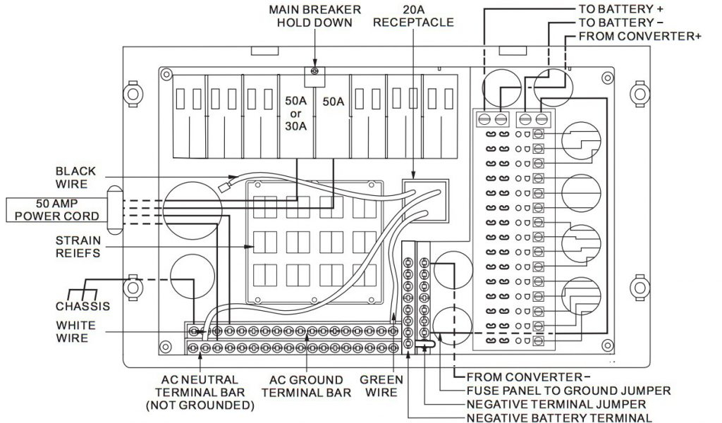
Main Components of an RV Converter Charger Wiring DiagramĪt the core of all RV converter charger wiring diagrams is the AC voltage source, the DC direct storage power centre, the fuse, the outlets, and the control point. This information helps to better understand which aspect is important to keep ahold of other related electronics, for example, like the battery – otherwise known as the manager of the current. These joints, workings, and links can also be understood better in relation to the components that form the balancing side of the scheme. From this detailing, the viewer can identify what and where every connection will be made and how they work in connection with each other. From here, the perspective will then move upward towards the junction hub where the circuit becomes most operational. The way to start off is by identifying the source of electricity, normally stated at the very bottom of the diagram. However, with a bit of patient observation and guidance, one can eventually learn how such schematics work. The sheer complexity of such diagrams can make it intimidating for a beginner to read with total understanding.
Progressive dynamics power converter wiring diagram how to#
How to Read an RV Converter Charger Wiring Diagram By regulating abilities and power output, this setup can be an increasingly important factor in preventing any unreliable readings or inconsistencies to ensure the most appropriate setting for the RV system. It is in large part due to the extra safety measures that need to be taken while designing such a system. Especially when it comes to a wiring diagram of an RV’s converter charger, these vital essentials become even more important. To get the best optimal electrical performance, astute planning and well-thought-out designs are aspects one should always bear in mind.

When talking about wiring diagrams, there is bound to be a deep dive into the intricacies involved. Exploring the Exacting Requirements for an RV Converter Charger Wiring Diagram


 0 kommentar(er)
